| Movable
Bridge Needs
According to information from the Federal
Highway Administration‘s data, there
are approximately 892 movable bridges in the
United States National Bridge Inventory (NBI)
on the public roads in the United States.
According to FHWA’s National Bridge
Inspection Standards approximately 589 (66%)
of these of these movable bridges are structurally
or functionally obsolete. This data does not
consider the need for movable bridges in new
locations.
Economic Issues
The cost to construct or reconstruct a movable
bridge can easily exceed the cost of a comparable
fixed bridge meeting similar design parameters
by 3 to 6 times. For example, a bascule drawbridge
recently constructed in Miami, Florida —
the Second Avenue drawbridge — costs
approximately $44 million while a comparable
fixed bridge without the vertical navigation
clearance requirements would have cost approximately
$10 million. Another example is the vertical
lift drawbridge under construction in Houma,
Louisiana — the Daigleville Bridge.
It costs approximately $6 million dollars
while a comparable fixed bridge without the
vertical navigation clearance requirements
costs approximately $1.5 million. Because
of the high costs of movable bridges, many
communities cannot afford to replace their
existing, deficient movable bridges or to
construct new movable bridges on navigable
stream crossings where needed.
The low-level movable bridge crossing is
the most common application for movable bridges
and the substantial part of the discussion
herein. A low-level movable bridge alternative
will typically have the lowest construction
cost and the highest daily operating costs
in terms of power consumption and manpower
required. Low-level movable bridge crossings
necessarily expose the movable span to collision
damage by the most massive components of marine
vessels that are nearest to the water surface.
This results in high economic losses due to
severity of the damage and loss of service
for the months that are necessary to effect
emergency repairs.
The high-level fixed bridge crossing is
an alternative to the low-level movable bridge
crossing. Due to its height above the water
— the vertical clearance required over
the navigation channel — the high-level
fixed bridge requires the construction of
substantial substructures and costly approach
structures making this alternative typically
a more expensive alternative to construct
than a low-level movable bridge. A high-level
fixed bridge normally takes substantially
longer to construct than a low-level movable
bridge and it can permanently disrupt a community
separated by a navigable waterway.
The semi-high-level movable bridge crossing
combines a movable bridge with longer approaches
to the semi-high-level crossing. It combines
some of the higher construction costs of the
high-level fixed bridge with the ongoing operating
costs of a low-level movable bridge making
this alternative usually the most expensive.
An intersecting high volume marine channel
and high traffic volume highway facility in
an urban environment, where limiting the frequency
of bridge openings to accommodate only the
larger vessels and a limited length of approach
structures is acceptable, this configuration
becomes feasible by the unique conditions
if not economically the best alternative considering
user costs.
Construction Issues
With the prevailing traffic conditions in
most communities, shutting down an existing
route segment on the public street system
for 2 to 4 years to reconstruct a movable
bridge is generally unacceptable. The aforementioned
Second Avenue drawbridge in Miami, Florida,
took over 2 years to construct. Similarly,
the Daigleville drawbridge in Houma —
expected to be completed by January 2004 —
will have taken nearly 3 years to construct.
For the Daigleville drawbridge, there has
been at least one petition filed by frustrated
businesses and property owners concerned about
its lengthy construction time. While construction
time for movable bridges may be expedited
as much as it is possible, it is not uncommon
that unanticipated, additional construction
time is required to deal with unexpected problems
associated with the complex nature of the
design and construction of the conventional
movable bridges.
History
Conventional Movable
Bridge Types
In his history of movable bridges, titled
Remember the Past to Inspire the Future
– Historic Development of Movable Bridges,
John A. Schultz, Jr., SE, reveals that the
modern versions of the three conventional
movable bridge types — namely the vertical
lift, bascule and swing drawbridges —
are 19th century developments. Each of the
conventional movable bridge types features
a unique movement including vertical translation,
vertical rotation and horizontal rotation
respectively.
One may ask, why did these bridge movements
become standards? From a review of bridge
history and given 19th century technology,
bridges with these three movements were the
easiest to construct, the most cost effective
and the most reliable to operate. It appears
that once these three standards were available,
the 19th century spirit of movable bridge
innovation may have faded into simply updating
and improving on the three standards.
Retractable Drawbridge
The retractable drawbridges — also referred
to as the traversing or sliding drawbridge
— has been designed and constructed
in the past. However, it never gained the
broad acceptance of the conventional moveable
bridge types — vertical lift, bascule
and swing drawbridges. A reason the retractable
drawbridge did not come into common use is
explained by F. C. Kunz, CE in his book, Design
of Steel Bridges — Theory and Practice
for the use of Civil Engineers and Students,
1915, in Chapter XIV on Movable Bridges and
Turntables page 275. He writes,
A traversing bridge is not desirable as it
requires more power than any other kind and
is slow of motion. It has been used in only
a few cases for railroad bridges, but has
proved satisfactory for small highway bridges.
Given the technology of 90 years ago, the
retractable drawbridge was apparently not
a technically or economically a competitive
choice. However, it is believed that the two
disadvantages expressed by Kunz — excessive
power consumption and a slow operation —
can be effectively overcome through invention
and using current technology. This will be
discussed later in more detail.
Existing Limitations
There are design requirements that tend
to make the conventional movable bridge types
— vertical lift, bascule and swing drawbridges
— expensive to build. To operate and
move the movable spans to a position that
provides the required unobstructed navigation
clearances, the conventional movable bridge
types typically require components of their
structures to be larger and/or more complex
than would otherwise be required of the comparable
fixed bridge necessary to span the navigation
channel and accomplish the intended traffic
carrying purpose.
The vertical lift drawbridge requires
the movable span to be translated vertically
enough to provide for the maximum vertical
navigation clearance required above the water.
To do this, it requires an expansive and massive
superstructure to support the span, counterweights,
sheaves, cables, and power and control equipment
to lift the movable span typically 50' to
a 100' or more vertically. This superstructure
is very expensive to build.
The bascule drawbridge requires
the movable span — a bascule leaf —
to be rotated vertically up and away from
the navigation channel to provide the maximum
horizontal navigation clearance and unlimited
vertical navigation clearance. Depending on
the depth of a bascule girder, the distance
between piers supporting the bascule girder
is typically greater than what is necessary
to meet the maximum horizontal navigation
clearance. Live load resistance provisions
— particularly for a double leaf bascule
drawbridge — and the counterweight configuration
typically result in a massive pier required
to support a bascule span.
The swing drawbridge requires the
movable span to be rotated horizontally parallel
to — and out of — the navigation
channel to provide the maximum horizontal
navigation clearance and unlimited vertical
navigation clearance. The swing span rests
on a turntable or pivot pier for which its
center and the center of rotation of the span
typically coincide and it must be horizontally
offset from the edge of the navigation channel
by more than half the width of the movable
span. This is necessary to locate the movable
span outside of the navigation channel when
in the opened position. As a result, a swing
drawbridge superstructure and substructure
are oversized to meet the offset and operation
requirements. Wider roadways require greater
offsets and therefore greater size for the
turntable pier and length of movable span
for the swing drawbridge. Because of the required
offset, swing drawbridges are normally best
suited for relatively narrow spans of those
providing for fewer traffic lanes. Of the
conventional movable bridge types, the swing
span drawbridge requires the most right of
way in which to operate the movable span.
Innovation
Considering the opportunities that may be
available in the use of 21st century technology,
and the specific needs of highway transportation
and the nature of highway transportation facilities
today; it is suggested that it may be the
right time to — as Shultz’s title
suggests — Remember the Past to
Inspire the Future. It may be time to
rekindle the 19th century spirit of movable
bridge innovation by leveraging 21st century
technology to address the functional and economic
needs of the 21st century.
Goals
Every movable bridge location has its own
unique site parameters that require consideration
in the design. When reviewing initial design
and construction costs, construction time,
maintenance and operations costs, and safety
issues both during and after construction,
it appears that the costs for every movable
bridge project has the potential to be reduced
substantially through innovation in movable
bridge design. For this reason, it is reasonable
that an innovation in movable bridge technology
should be sought outside of the three conventional
movable bridge types. Such an innovation should
provide a high quality facility that can be
constructed, operated and maintained easily;
provided at a significant cost savings; and
constructed in a minimum time.
Could there possibly be an innovative movable
bridge design that may be equal to or more
effective than the time-tested conventional
movable bridge types and yet draws on the
knowledge base developed for them? If there
is such a type of movable bridge, it most
likely would be discovered through the aforementioned
tenet, Remember the Past to Inspire the Future,
and in doing so, the best conventional features
would be extracted. The effectiveness of any
type of movable bridge measured against the
conventional movable bridge types is in the
context of true practical worth relative to
• cost to design and construct
• time to construct
• cost and speed of operation
• cost and frequency of maintenance
and
• general safety concerns.
In his book titled, Design of Steel Bridges
— Theory and Practice for the use of
Civil Engineers and Students, 1915 in
Chapter XIV on Movable Bridges and Turntables
page 273 F.C. Kunz, CE, writes
It is impossible to give any general rule
as to which kind of bridge is best adapted
in a certain case, as there are many factors
to be considered. The following general principles
should be observed:
(1) When the bridge is closed it should be
as nearly as possible a fixed span.
(2) The machinery should be designed so that
the bridge can be easily operated while moving.
The most simple design which gives the least
first cost and cost of operation is the best.
(3) The structural and machinery parts of
the bridge should be separate; that is, when
the bridge is closed, acting as a fixed span,
the machinery parts should not receive any
stress.
Lift-Slide Drawbridge
The economic and construction issues experienced
with the conventional movable bridge types
suggest that there may be a niche for a lower
cost movable bridge type. It is proposed that
a retractable drawbridge innovation, the lift-slide
drawbridge - patent pending, may offer a lower
cost alternative to the conventional movable
bridge types. Its principal benefit appears
to be reducing the construction costs by an
estimated 30 to 50 percent making movable
bridge projects more affordable. Some broad
goals achievable with this simple, innovative
drawbridge design are
• free up millions of transportation
dollars to fund additional, badly-needed highway
transportation projects
• accelerate the construction process
reducing construction time to a year or less
and
• allow opportunity for improvement
in movable bridge operation, maintenance and
safety.
The lift-slide drawbridge with a unique variable
load counterweight system — patent pending
— was conceived to meet the above goals
in addition to incorporating the best features
and avoiding the disadvantages of the conventional
movable bridge types. The anticipated features
of the lift-slide drawbridge are
• a high quality, safe highway bridge
• rapid and simple operation
• accessible components for safe and
easy maintenance
• low maintenance requirements —
as a fixed span, machinery parts do not support
loads
• can be maintained while in service
• can be constructed without disrupting
marine traffic
• can be constructed safely and quickly
• unlimited vertical clearance for marine
traffic
• structure is well protected from damage
by marine traffic
• is scalable in width so that it can
be designed to accommodate one to six lanes
of traffic
• is scalable in length so that it can
accommodate a horizontal navigation clearance
up to 150' and perhaps more
• is scalable in duty so that it can
be designed to accommodate light or heavy-duty
traffic
• can be built inexpensively (scalability
in width, length and duty makes it possible
for a drawbridge to be sized to meet the needs
of a location with a resultant substantial
cost savings)
• can be built within existing or minimal
right-of-way, and
• the structure is attractive, low profile
and would be welcome in any neighborhood.
Invention
The main components of the lift-slide drawbridge
invention include
• the movable or retractable span
• the lifting apparatus in the lift-slide
mechanism,
• the variable load counterweight system
in the lift-slide mechanism and
• the sliding apparatus in the lift-slide
mechanism.
The anticipated advantages of the retractable
drawbridge previously discussed can be realized
with the development and deployment of the
lift-slide drawbridge described. The lift-slide
drawbridge design will be a simple, yet rapid
operating, retractable drawbridge. By providing
a short initial vertical lift of the retractable
span to clear the adjacent bridge approaches,
the conflict between them is avoided. The
lifting of the heavy retractable span led
conceptually to an energy efficient and cost
effective scissors lift apparatus assisted
by a variable load counterweight system. The
resulting reduced power consumption expected
allows the use of smaller motors for the system
with overall cost savings. The power consumption
for operating the lift-slide drawbridge is
expected to be similar to — or possibly
less than — that for the conventional
movable bridge types.
Unlike the conventional movable bridge types,
the lift-slide drawbridge operation will not
generally require components of their structures
to be larger and/or more complex than would
otherwise be required of the comparable fixed
bridge necessary to span the navigation channel
and accomplish the intended traffic carrying
purpose. This is because
• the operation of its movable span
is within its plan limits
• the open position for the movable
span that provides unobstructed navigation
clearances coincides with the approach spans
• the substructure components will be
approximately the same size as that required
for a fixed bridge and
• the movable span (deck) components
will be approximately the size of those for
a fixed bridge.
 |
| |
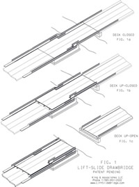
Movement
The lift-slide drawbridge is a movable bridge
invention that when it is supporting roadway
traffic it is a two-span continuous structure.
When roadway traffic is not present and it
is being operated (retracted), it is an equal-arm,
cantilever beam structure. Operationally,
it is initially lifted (translated) vertically
to an elevation that will clear it over the
adjacent approach spans, then it is retracted
from the navigation channel by sliding (translating)
it horizontally back over the adjacent approach
span.
The three operating positions of the bridge
follow in more detail:
• In the down-closed position as shown
in Figure 1a with roadway traffic present,
the bridge is a two-span continuous beam structure
supported directly on its by piers with one
span over the navigation channel.
• In the up-closed position as shown
in Figure 1b with roadway traffic not present,
the bridge is an equal-arm cantilever beam
structure supported on the lift-slide mechanism
with one cantilever span over the navigation
channel and lifted vertically by the lift-slide
mechanism high enough to clear the adjacent
spans on the bridge approach and any other
obstacles when the span is retracted horizontally
from the navigation channel.
• In the up-open position as shown in
Figure 1c with roadway traffic not present,
the bridge is an equal-arm cantilever beam
structure supported on the lift-slide mechanism
and retracted horizontally from the navigation
channel with one cantilever span over the
adjacent spans on the bridge approach. As
a design alternate, in up-open position the
adjacent approach spans may be used to support
the bridge deck by means of rollers attached
to the underside of the retractable span.
 |
| |
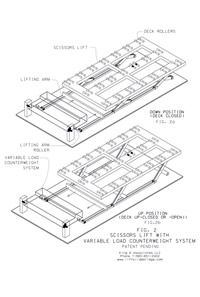
Operation
When in the down-closed position, the retractable
span is supported directly by the piers and
functions as a two-span continuous beam fixed span for live loads.
To operate the span, roadway traffic service
is ceased and the vertical lift apparatus
the lift-slide mechanism is activated. It
is a hydraulically driven scissors lift apparatus
used in conjunction with the variable load
counterweight system to provide an effective
means to lift the retractable span typically
2.5' to 5.0' to clear adjacent approach spans
as shown in Figures 2a and 2b.
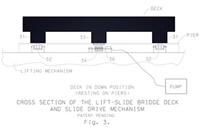
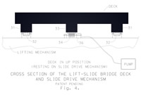
Once in the up-closed position, the equal-arm
cantilever beam structure is supported by
the slide-lift mechanism the sliding apparatus
driver is activated to retract the cantilevered
span translating it horizontally to the up-open
position thus opening the navigation channel
to marine traffic. The sliding apparatus is
secured atop the lift-slide mechanism and
coupled to the bottom of the retractable span.
It allows the retractable span to slide or
translate horizontally over the adjacent approach
spans and the navigation channel while in
the up position as shown in Figures 3 and
4.
 |
| |
| |
 |
| |
Following the item numbers shown in Figures
3 and 4 and in braces in this text, the sliding
apparatus driver consists of a span rack [33]
attached to the underside of the retractable
span. It is engaged by a span pinion [34]
coupled to a span drive motor [36] that are
both attached to the lift-slide mechanism.
The retractable span is guided by span guides
[31] that are attached to the underside of
the retractable span seated in flanged wheel
trucks [32] that are attached to the lift-slide
mechanism.
Variable Load Counterweight
Movable bridges having a vertical lift motion
require a counterbalance to effectively and
safely handle the heavy load of the movable
span. The only practical counterbalance design
for the large vertical movements of a vertical
lift drawbridge is counterweights suspended
by cables passing over sheaves supported at
the top of lift towers. Since the lift-slide
drawbridge only requires the lifting of its
retractable span a few feet, the traditional
counterweight design if feasible would appear
to be a prohibitively expensive and complex,
so a simple innovative counterweight system
was invented.
 |
| |
| |
 |
| |
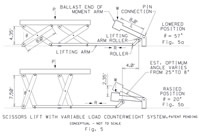
The variable load counterweight system shown
in Figures 5 and 6 is a counterweight designed
to counter the characteristic forces inherent
in operating the scissors lift apparatus proposed
to lift the span. This is done by providing
a counterweight coupled to the scissors lift
apparatus via its lifting arm. The counterweight
is mounted on — and cantilevered from
— a hinged support and supported by
a lifting arm attachment roller.
Raising or lowering of the scissors lift
apparatus moves the lifting arm attachment
roller support point on the counterweight
and thereby varies the length of the moment
arm to the ballast end of the counterweight.
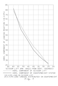
The change in length of the moment arm between
the lifting arm attachment support point roller
and the ballast end of the counterweight is
designed to vary the force applied to the
lifting arm to correspond closely with the
variation in the force required to rise and
lower the scissors lift apparatus (See Figure
7). In this way, the variable load counterweight
system is designed to effectively counterbalance
the forces in the system throughout the full
range of movement.
 |
| |
The application of a variable load counterweight
system, coupled with a scissors lift apparatus,
provides a very simple means to counterbalance
the large variable forces encountered in operating
the scissors lift apparatus used to lift the
heavy retractable span. The design of the
variable load counterweight system requires
that the counterweight weigh 25 to 30 percent
of the weight of the retractable span to be
lifted. This compares to the weight of the
counterweights for a vertical lift drawbridge
— 100 percent of the weight of the span.
This is a substantial material cost savings
when considering that a typical span may weigh
250 to 1000 tons or more.
The advantages of a properly configured variable
load counterweight system coupled to the scissors
lift apparatus are
• less dead weight - In a variable load
counterweight configuration, a moment arm
is formed between the counterweight ballast
and the lifting arm creating a mechanical
advantage that magnifies the ballast load
on the said lifting arm roller allowing for
less ballast than would otherwise be required
to counterbalance the forces in the system.
• simplicity - The design is very simple
with few parts making it easy to fabricate,
install and maintain.
• reduced cost - The overall cost of
design, fabrication, materials and installation
is a fraction of that of the other methods
considered.
• reduced installation time - The time
required to install the variable load counterweight
system is also expected to be a fraction of
the time required for conventional systems.
• flexibility - The variable load counterweight
system can be configured in a multitude of
ways to effectively meet the counterbalance
needs of a specific project.
• efficiency - The variable load counterweight
system makes practical the employment of a
scissors lift (or similar) apparatus for the
lifting of very heavy loads.
Configurations
It is foreseen that there will be two configurations
of the lift-slide drawbridge — the single
leaf configuration and the double leaf configuration.
To cross the larger navigation channels, twin
opposing lift-slide drawbridges are positioned
opposite each other and the extended leaves
of the cantilevered spans are connected by a
shear lock and then lowered simultaneously onto
their piers creating a double leaf lift-slide
drawbridge as shown in Figures 8a and 8b. In
the down-closed position, the double leaf configuration
will be a three-span continuous beam with a
hinge at the midpoint of the center span and
provisions for live load uplift on the end supports.
It is anticipated that the single leaf lift-slide
drawbridge will be practical for navigation
channels up to 75' fender-to-fender clear
width. The double leaf lift-slide drawbridge
will be practical for navigation channels
from approximately 75' and greater fender-to-fender
clear width.
Conclusions
The lift-slide drawbridge is expected to
require less technical effort to design than
the conventional movable bridge types and
its fabrication is expected to require only
the standard tools and processes in a well
equipped machine and fabrication shop. It
is a low-tech solution with expected construction,
operating and maintenance costs to be equal
to or lower than the conventional movable
bridge types while using conventional components
and materials. The construction and operations
requirements for a lift-slide drawbridge should
be greatly reduced compared with those of
the conventional movable bridge types. Perhaps
more importantly, the construction time is
estimated to be approximately one year cutting
the construction time by at least half that
of the conventional movable bridge types.
The process for biding and letting a project
for a lift-slide drawbridge is expected to
be similar to that for any bridge construction
project.
With the prospective advantages of the lift-slide
drawbridge, preliminary estimates indicate
the construction cost will be approximately
50 to 70 percent that of a conventional vertical
lift drawbridge. Consider for example the
$6 million Daigleville Bridge in Houma —
the aforementioned drawbridge now under construction.
According to preliminary cost estimates, the
cost to construct a lift-slide drawbridge
at that site would be approximately $3.5 million
or a 40 percent savings.
The aforementioned $44 million Second Avenue
drawbridge in Miami, Florida — a bascule
bridge — was constructed with 2,300
tons of structural steel and 2,400 tons of
counterweight ballast steel. A lift-slide
drawbridge design constructed at the site
could reduce the structural steel by 15% and
the counterweight ballast by 70% for a total
estimated reduction in steel of 2,025 tons.
Assuming steel costs an average of $4,000
per ton, this structure would save $8 million
or 18 percent less to construct.
The cost saving in fabrication methods associated
with the lift-slide drawbridge was not considered
in these estimates. A more refined cost analysis
comparison obtained from a complete preliminary
design of a comparable lift-slide drawbridge
design and a conventional movable bridge type
at the same site will better reveal the particular
cost savings.
With continued development, there is reasonable
confidence that the lift-slide drawbridge
will become a new cost effective, functional
and versatile movable bridge type added to
the mix of the conventional movable bridge
types. It is expected to compete well and
it may become the first choice among alternatives
for most movable bridge projects.
Supplement: Variable Load
Counterweight System
To simplify the lifting components and minimize
the cost and effort required to lift the movable
span of the lift-slide drawbridge, the variable
load counterweight system (VLCS) was conceived
in conjunction with the scissors lift apparatus
(SLA) and it is in the early stages of development.
The mechanics of the VLCS are based on a relatively
simple mechanical lever principle. The findings
presented are preliminary and based on computer
analysis and 1/6 scale model testing. The
VLCS will provide:
• neutral stability counterweight function
for the SLA for the full range of its movement
• minimum power requirements as a result
of the counterweight function and
• level power requirements throughout
the operating cycle.
To design an adequate counterweight system
for the SLA three issues need to be resolved.
• The counterweight and SLA force to
lift the span are in neutral equilibrium over
the full range of the SLA movement.
• The amount of power required and its
associated cost to lift the span in approximately
30 seconds is minimized.
• The cost and time to construct the
counterweight system equal to or less than
that provided with the conventional movable
bridges; and its ongoing maintainability must
be equal to or better than that provided with
the conventional movable bridges.
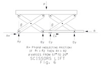
To explain the mechanics behind the coupled
scissors lift apparatus and variable load
counterweight system (SLA/VLCS) it must
be envisioned how the SLA is actuated. The
horizontal and vertical force components of
the reaction from the weight of the span through
the SLA are shown in Figure
6. Following the schematic diagram shown
in Figure 6, the equilibrium of the SLA will
be maintained for its full range of movement
by opposing P; the total horizontal component
of the reactions resisting P, the weight of
the span and the SLA.
The total horizontal component of the reaction
R, is a function of the angle of the scissors
lift arm from the vertical 2, where R = P
tan(2). Given the full range of the SLA is
20E#2 #57E then for all values of
2 1 > 2 2 the corresponding
values of R1 > R2
consistently throughout the defined full range
of the SLA movement. A mechanism is needed
that will continuously apply a horizontal
force !R to oppose the horizontal component
of the reaction R over the full range of horizontal
movement of the SLA. This would place the
system in continuous neutral equilibrium over
the full range of the SLA movement.
The VLCS/SLA as shown in Figure
5 was specifically designed to produce
continuous neutral equilibrium over the full
range of the SLA movement. When the SLA is
in the down position as shown in Figure
5(a), the lifting arm roller is forced
toward the counterweight pin connection in
continuous contact with the counterweight
arm resulting in a large force directed approximately
25E from vertical producing a horizontal component
to oppose the total horizontal component of
the reaction R in the SLA resisting the weight
P of the span and the SLA. When the SLA is
in the up position as shown in Figure
5(b), the lifting arm roller is drawn
away from the counterweight pin connection
while in continuous contact with the counterweight
arm resulting in a much smaller force directed
approximately 8E from vertical producing a
horizontal component to oppose the much smaller
horizontal component R of the reaction in
the SLA resisting the weight P of the span
and the SLA.
It can be appreciated that the opposing
horizontal force produced by the VLCS will
vary continuously between the lowered and
raised position of the SLA. By design this
will produce a continuously varying horizontal
force that approximates the continuously varying
horizontal forces produced by the horizontal
component of the reaction R in the SLA throughout
its full range of movement as is the case
and shown in Figure 7.
This results in the approximate neutral equilibrium
throughout the full range of movement of the
SLA.
The SLA/VLCS is a system of connected rigid
bodies with one degree of freedom. To exchange
potential energy between the VLCS and the
SLA, there must be vertical movement of the
counterweight. This vertical movement is enabled
by the hinge support of the cantilevered counterweight
of the VLCS. To assure the potential energy
is exchanged between the SLA and the VLCS
through the lifting arm, the lifting arm roller
support relies on the SLA for stability. The
potential energy is exchanged between the
VLCS and the SLA through the horizontal force
and associated movement in the lifting arm
that couples the two.
An approximately 1/6 scale model of the
SLA/VLCS was built and initial tests using
it are consistent with the previous explanation
of the mechanics. The scale model was constructed
with a 38 lb. counterweight physically cantilevered
7.66 feet with a center of mass including
the arm located 4.00 feet from its pin connection.
A series of tests were conducted with approximately
150 lbs. simulating the weight of the span
and the SLA.
In the first test, the VLCS was uncoupled
from the SLA and the horizontal reaction R
required to lift the span and the SLA over
the full range of movement of the SLA (25E#2
#54E) was observed. The maximum horizontal
reaction R required to lift the span and the
SLA over its full range of movement was greater
than 150 lbs.
In the second test, VLCS was coupled to
the SLA suspending the 38 lb. cantilevered
counterweight on the lifting arm roller. With
no additional weight added to the cantilevered
counterweight, the maximum additional horizontal
force required to lift the SLA over its full
range of movement was reduced to 140 lbs.
In the third test an additional 37 lbs.
weight was placed on the cantilevered counterweight
arm at a position 7.66 feet from its pin connection
resulting in a center of mass located approximately
5.8 feet from the counterweight pin connection.
The maximum additional horizontal force required
to lift the SLA over its full range of movement
was 30 lbs. and the SLA/VLCS was operating
in neutral equilibrium. A summary of additional
test results is provided in Table
1.
At the neutral equilibrium achieved in the
third test, the SLA/VLCS model provided a
80% reduction in energy requirement compared
with the SLA uncoupled from the VLCS. If similar
results are obtained on a full scale, movable
bridge with a span and SLA structure weighting
300 tons the power required to lift the deck
3.5 feet in 30 seconds would be approximately
29 horsepower delivered with 4 - 6" diameter
hydraulic rams at 1200 psi.
In another series of tests, it was observed
that the force required to lift the SLA dropped
in proportion to the weight added to the cantilevered
counterweight. Weight was incrementally added
to the counterweight until the SLA/VLCS began
operating in neutral equilibrium. The maximum
force required to lift the SLA was approximately
1.5 of the calculated frictional forces in
the system. More weight was incrementally
added to the counterweight and the SLA/VLCS
continued to operate in neutral equilibrium
until the force to lift the SLA was reduced
to zero and the SLA tended to lift on its
own. These observations demonstrate that the
SLA/VLCS operates in neutral equilibrium over
a large variation in the weight of the cantilevered
counterweight.
 |
| |
In conclusion, the VLCS appears to favorably
resolve the 3 previously stated issues. It
balances the forces to lift the span and the
SLA in neutral equilibrium over the full range
of movement of the SLA. It provides an energy
efficient mechanism that can readily lift
a bridge span and SLA 3 to 5 feet in 30 seconds.
The hope of minimum cost and time to construct
and good maintainability of the SLA/VLCS would
appear to be in the evident simplicity demonstrated
in the details provided.
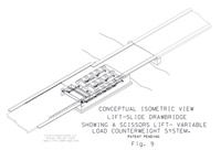
Figure 9 shows an isometric view of the SLA/VLCS
installed in a Lift Slide Drawbridge.
Table 1
|
Neutral
Equilibrium Test Data from an Approximately
1/6 Scale Model of the Coupled Scissors
Lift Apparatus and Variable Load Counterweight
System (Patent Pending)
Angle of the scissors lift apparatus
varies from 54E to 25E from vertical.
Angle of cantilever counterweight arm
varies from 16.7E to 8.4E from horizontal.
|
|
Load
on SLA (1) |
Load
on CWA (2) |
Max.
force reqd. to lift SLA (3) |
Max.
force reqd. to lower SLA (4) |
Dist.
from pin to CWA center of mass (5) |
Dist.
from pin to CWA roller (6) |
(2)/(1)
(7) |
(3)/(1)
(8) |
|
lbs. |
lbs. |
lbs. |
lbs. |
feet |
feet |
ratio |
ratio |
|
100 |
50 |
20 |
15 |
5.0 |
0.52 |
0.5 |
0.2 |
|
100 |
70 |
20 |
15 |
4.0 |
0.52 |
0.7 |
0.2 |
|
100 |
100 |
20 |
15 |
2.5 |
0.52 |
1.0 |
0.2 |
|
150 |
75 |
30 |
20 |
5.8 |
0.52 |
0.5 |
0.2 |
|
SLA - Scissors lift apparatus CWA
- Counterweight Arm
(3) Note: For all test sets, the system
is in neutral equilibrium.
(7) Note: As the distance from the pin
to the CWA center of mass increases,
the ratio of the load on the CWA to
the load on the SLA weight increases.
Note: On a working system the load on
CWA will likely be 25 to 33 percent
of the load on SLA. |
About The Author
Rex J. King, Jr., PE, is President of King &
Associates LLC, Civil, Structural and Consulting
Engineers he founded in 2000. He earned his
BS in Civil Engineering in 1993 from Louisiana
Tech University. A licensed professional engineer
in Louisiana — King has planned and designed
numerous civil and structural engineering projects
in Louisiana and he is the inventor of the lift-slide
drawbridge — patent pending — and
the variable load counterweight system —
patent pending — the subject of this article.
King is currently President of the Bayou Chapter
of the LES and a member of the ASCE, LES, NSPE,
AISC, HMS and other engineering related organizations.
|